WGB
New Member
Even though some of us grew up with drum brakes the 116 handbrake is fiddly and time consuming to repair as it is small and hidden behind the large flange of the hub.
Faults I have personally encountered in 116/126 land include sticking mechanism causing the shoes to burn out and a rusted and frozen left rear cable from outer casing damage caused by exhaust heat which then lets in water. This car had no particular issues and had a good healthy original handbrake but I have protected the part of the cable that runs near the exhaust with heat resisting silver tape.
There is a precise order for re-assembly noted in the workshop manual and I have used this after stuffing around for about three hours trying to get one brake back together (I finally read the book).
Here are the right rear brake components including original shoes laid out as seen from the backing plate side with front to the left of picture.
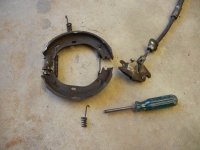
The cable and it's components changed with the 1975 update and this is a later cable with the stirrup on the cable end rather than in the mechanism itself.
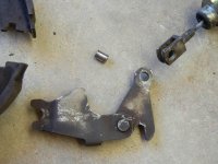
A pin is used to join the cable with the expander
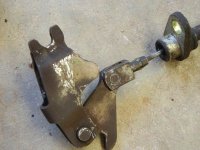
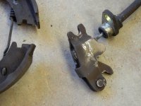
When the the extender mechanism is in it's functioning position the pin is held by the sides of the expander.
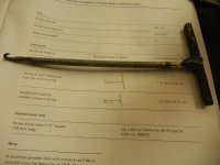
Two special tools are mentioned in the manual. Here is the first which I have made by cutting off the end of an old phillips head screwdriver and cutting a vertical slit in the end with a cutting disc in an angle grinder.
It is used to grip and turn the stabilising springs.
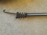
The second is a hook - again made from the shank of an old phillips head screwdriver which is used to pull the main spring into it's final position.
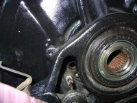
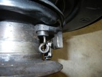
This is the hole in the backing plate through which the cable passes.
And is held by an allenbolt.
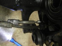
This allenbolt is usually quite tight and access can be a little difficult so it is not unusual to round out the head trying to remove it hence I have replaced both with new bolts and washers.
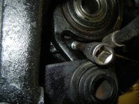
Here is the cable in it's final position.
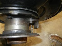
The cable can be pulled through and the expander mechanism attached to the end.
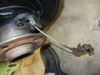
And the cable pulled back.
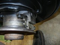
The main spring is then placed in position but remember it is not symmetrical and the top loop is larger than the bottom loop to allow for ease in re-assembly.
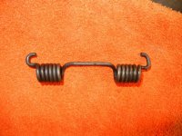
It can be a squeeze to get it into this position.
The shoes adjustor and smaller spring are then assembled and the open end stretched over the hub
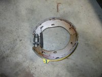
And placed in postion on the hub aligned with the expander.
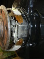
The top and bottom stabilising spring clips have to be engaged in these slots which are parallel to the ground and found top and bottom on the backing plate.
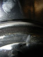
The modified screwdriver works a treat first with the top clip.
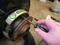
And then with the bottom clip.
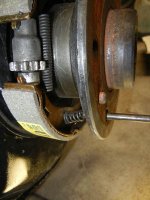
The main spring is jiggled until the bottom tag fits in the lower shoe and then using the hook (or a small strong screwdriver) the larger top end is forced into the slot in the top shoe.
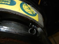
And then the spring is snapped into final position.
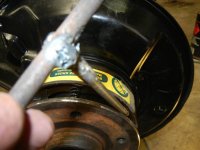
Here is the final view from the front.
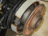
And the back.
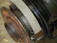
The new disc was fitted with anti-seize paste so that if it ever needs opening again it should be easier (This is a recommendation for the same job in the M-B WIS 126 section).
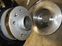
New discs also complete the all new look.
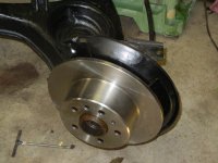
I might add the dics were $55 each and the set of hand brake pads were $50 for the set.
Bill
Faults I have personally encountered in 116/126 land include sticking mechanism causing the shoes to burn out and a rusted and frozen left rear cable from outer casing damage caused by exhaust heat which then lets in water. This car had no particular issues and had a good healthy original handbrake but I have protected the part of the cable that runs near the exhaust with heat resisting silver tape.
There is a precise order for re-assembly noted in the workshop manual and I have used this after stuffing around for about three hours trying to get one brake back together (I finally read the book).
Here are the right rear brake components including original shoes laid out as seen from the backing plate side with front to the left of picture.

The cable and it's components changed with the 1975 update and this is a later cable with the stirrup on the cable end rather than in the mechanism itself.

A pin is used to join the cable with the expander

When the the extender mechanism is in it's functioning position the pin is held by the sides of the expander.

Two special tools are mentioned in the manual. Here is the first which I have made by cutting off the end of an old phillips head screwdriver and cutting a vertical slit in the end with a cutting disc in an angle grinder.
It is used to grip and turn the stabilising springs.

The second is a hook - again made from the shank of an old phillips head screwdriver which is used to pull the main spring into it's final position.

This is the hole in the backing plate through which the cable passes.

And is held by an allenbolt.

This allenbolt is usually quite tight and access can be a little difficult so it is not unusual to round out the head trying to remove it hence I have replaced both with new bolts and washers.

Here is the cable in it's final position.

The cable can be pulled through and the expander mechanism attached to the end.

And the cable pulled back.

The main spring is then placed in position but remember it is not symmetrical and the top loop is larger than the bottom loop to allow for ease in re-assembly.

It can be a squeeze to get it into this position.

The shoes adjustor and smaller spring are then assembled and the open end stretched over the hub

And placed in postion on the hub aligned with the expander.

The top and bottom stabilising spring clips have to be engaged in these slots which are parallel to the ground and found top and bottom on the backing plate.

The modified screwdriver works a treat first with the top clip.

And then with the bottom clip.

The main spring is jiggled until the bottom tag fits in the lower shoe and then using the hook (or a small strong screwdriver) the larger top end is forced into the slot in the top shoe.

And then the spring is snapped into final position.

Here is the final view from the front.

And the back.

The new disc was fitted with anti-seize paste so that if it ever needs opening again it should be easier (This is a recommendation for the same job in the M-B WIS 126 section).

New discs also complete the all new look.

I might add the dics were $55 each and the set of hand brake pads were $50 for the set.
Bill
